Published August 16, 2026
Beyond the Cartesian Grid: A Fresh Take on Plotting
Pen plotters have experienced a massive renaissance in the DIY and maker communities over the past decade. Most of these machines utilize a standard Cartesian coordinate system, where a pen carriage moves along a linear X-Y gantry, and a small servo lifts the pen along the Z-axis. While highly reliable and relatively simple to program, these designs can feel somewhat repetitive to seasoned robotics and embedded electronics enthusiasts.
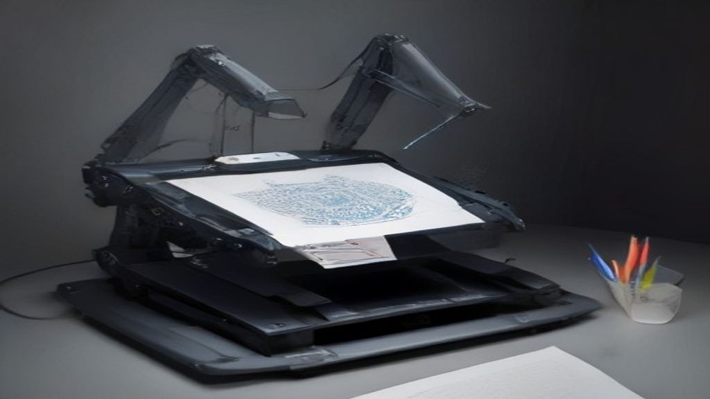
Maker András Vujovits decided to break away from this convention. Instead of relying on traditional linear rails, Vujovits reimagined the drawing machine by constructing a custom DIY pen plotter that utilizes delta kinematics and features an integrated automatic tool changer. The result is a highly dynamic, mesmerizing machine that challenges standard approach to DIY computer numerical control (CNC) art.
The Mechanics of Delta Kinematics
To understand why this project is so compelling, we must first look at how delta kinematics operate. Unlike Cartesian systems that move along perpendicular linear rails, a delta robot consists of three parallel arms connected to a stationary base at the top and a moving platform (the end effector) at the bottom.
There are several distinct advantages to using a delta configuration for a drawing machine:
- Reduced Moving Mass: In a Cartesian plotter, the motors driving the axes often have to travel along with the gantry. With a delta robot, the heavy stepper motors remain permanently fixed to the outer frame. The only moving parts are the lightweight carbon fiber or aluminum arms and the end effector.
- High-Speed Operation: Because the moving mass is minimized, delta mechanisms can achieve incredibly high acceleration and travel speeds without causing frame vibration or losing steps.
- Fluid Dynamics: Watching a delta robot work is highly organic; the jointed arms move in concert to position the pen, offering a visual spectacle that standard Cartesian gantries cannot match.
For an electronics engineer or embedded programmer, implementing delta kinematics presents a fascinating software challenge. Instead of translating a simple coordinate directly to step pulses, the system must perform real-time inverse kinematics calculations. To draw a simple straight line, the microcontroller must continuously calculate how the angles of all three independent arms must change relative to one another at every millisecond of the movement.
Solving the Single-Color Bottleneck with a Tool Changer
Aside from its rapid mechanical movement, Vujovits' plotter solves one of the most frustrating limitations of consumer-grade plotters: multi-tool operations. Traditionally, if you want to draw a design with multiple colors or varying line weights, you must pause the machine, manually swap the pen, recalibrate the height, and resume the job. This manual process is tedious and prone to alignment errors.
Vujovits overcame this by designing an automatic tool-changing system. The plotter features a dedicated docking station at the edge of its drawing boundary where multiple pens are stored. The end effector is designed to pick up, lock, unlock, and deposit these pens autonomously.
Achieving this requires incredible mechanical repeatability. A variation of even a fraction of a millimeter during a tool swap would ruin a complex drawing. To make this work reliably, maker-built tool changers often employ a combination of the following techniques:
- Kinematic Coupling: Using precisely positioned magnets and metal balls (or indexing pins) to ensure that when a tool is picked up, it settles into the exact same physical orientation every single time.
- Mechanical Locks: Utilizing miniature servo motors or passive spring-loaded latches that lock the tool in place during high-speed drawing sweeps, and release it when docked back in the holster.
- Firmware Offsets: Programming specific coordinate zones in the controller firmware where the machine knows to perform the "dock" and "undock" macros.
The Electronics and Firmware Under the Hood
To coordinate the three main stepper motors responsible for delta movement, alongside the actuators needed for the pen lift and the tool changer, a robust embedded control system is required. While standard 8-bit microcontrollers can handle simple linear movements, the heavy math involved in real-time delta inverse kinematics benefits immensely from 32-bit processing power.
Modern DIY builds of this caliber typically run on 32-bit control boards equipped with ARM Cortex-M microcontrollers. Firmware platforms such as Klipper, RepRapFirmware, or highly optimized versions of Marlin handle the heavy lifting. These firmware packages natively support delta geometry, allowing the user to input physical dimensions (such as arm length and end-effector radius) to automatically calibrate the motion profiles.
Additionally, silent stepper drivers (like the TMC2209 series) are critical. These drivers use advanced microstepping algorithms to ensure that the three tower motors operate silently and with minimal vibration, which is essential for laying down smooth, consistent ink lines without jagged artifacts.
Why This Project Matters to the Maker Community
The delta pen plotter by András Vujovits is a brilliant example of how industrial robotics concepts can be scaled down and democratized using open-source electronics, 3D printing, and creative engineering. It serves as an excellent reference project for students, robotics developers, and embedded engineers alike.
By combining parallel kinematics with automated tool swapping, this project demonstrates that DIY machinery doesn't have to be limited to the same Cartesian boxes we have been building for years. It encourages makers to explore complex mathematics, precise mechanical alignment, and creative tool design, raising the bar for what a home-built drawing machine can achieve.


0 comments:
Post a Comment